The EPAC Project continues to make good progress, with installation, design work and commissioning all now running in parallel. Some recent highlights are detailed below.
Find out more about this project on the EPAC information pages .
Commissioning of the EPAC 120 J Pump Amplifier
The Pump amplifier is situated on the second floor of the EPAC building. All the main components for this system – the Front End fibre amplifier and preamplifiers 1 and 2 (Figure 1), the 10 J pump diodes and blast shields (Figure 2), the 120 J pump diodes and blast shields, and the 10 J and 120 J cryostats and amplifier heads – have now been installed in the EPAC Pump room. Figure 3 shows a view of the Pump room components and service infrastructure.
Optics for the Front End have been installed and the CW beam has been aligned to the input of the 10 J amplifier. The 10 J CW beam has been aligned through all the passes, and onto all seven diagnostic channels. The optics for the 10 J to 120 J beam transport have been fitted, and the CW beam has been aligned to the input of the 120 J amplifier stage. All of the optics for the 120 J have now been fitted, and each of the two 120 J pump diodes is operating at 350 kW.
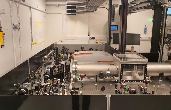
Figure 1: EPAC Front End setup for the 120J pump amplifier
![]()
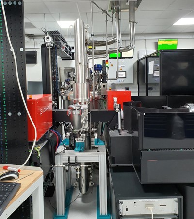
Figure 2: EPAC 10 J pump diodes and blast shields
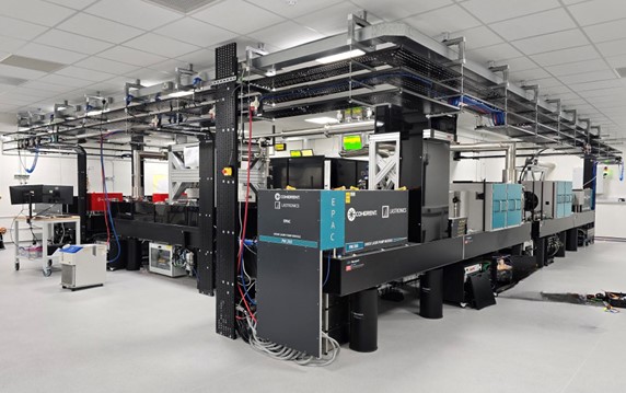
Figure 3: EPAC Pump room showing the 10 J and 120 J pump diodes and blast shields, and the service infrastructure
Meeting the challenge: installing the EPAC compressor chambers
The EPAC compressor chambers house large diffraction grating optics to handle the optical power of the petawatt pulses to be delivered to the Experimental Areas. In these chambers, the duration of EPAC pulses will be compressed by a factor of more than 100,000 to less than 30 fs duration. The laser beam must be propagated in a high vacuum during and after compression, so these compressor chambers act as the vacuum boundary. This vacuum environment is designed to be very clean and mechanically stable, and will enable highly precise motorised movements of the compressor optics. As the chambers need to withstand the large external forces imposed by atmospheric pressure, they are made from stainless steel, with suitably thick walls and reinforcing structures to prevent deformation. The doors are made from aluminium to reduce their mass, and the overall mass of the chambers. Even so, the mass of each chamber and internal breadboard is 13 tonnes, with an external size of 2.2 m x 3.2 m x 2 m.
The compressor chambers needed to be located on the second floor of the EPAC building. As there was no access through the roof, they were posted through an opening in a wall on that floor. The installation was completed in stages: concrete preparation works; baseplate positioning and permanent fixture to the concrete; lifting and positioning of the chambers; final assembly; and vacuum commissioning.
The work was completed by the CLF's dedicated team of technicians, with support from the ISIS survey team and specialist skills from four different engineering contractors. The planning and preparation works undertaken by the team allowed the final lifting, placement and assembly of the chambers to be completed in only four days, with the chambers positioned with millimetre accuracy!
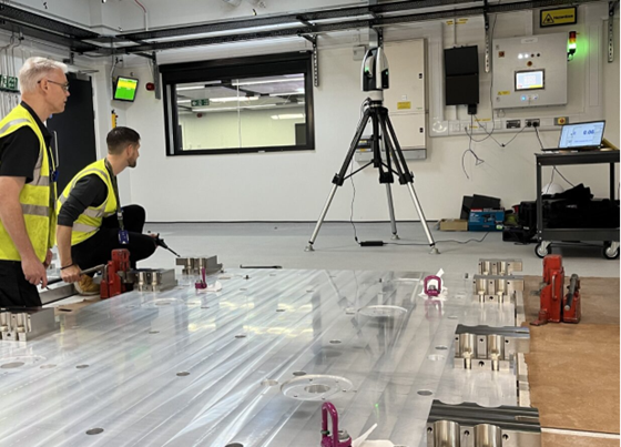
Figure 4: Positioning the baseplate
![]()
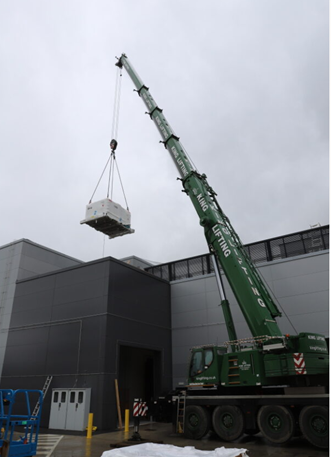
Figure 5: Lifting a compressor chamber to roof height
![]()
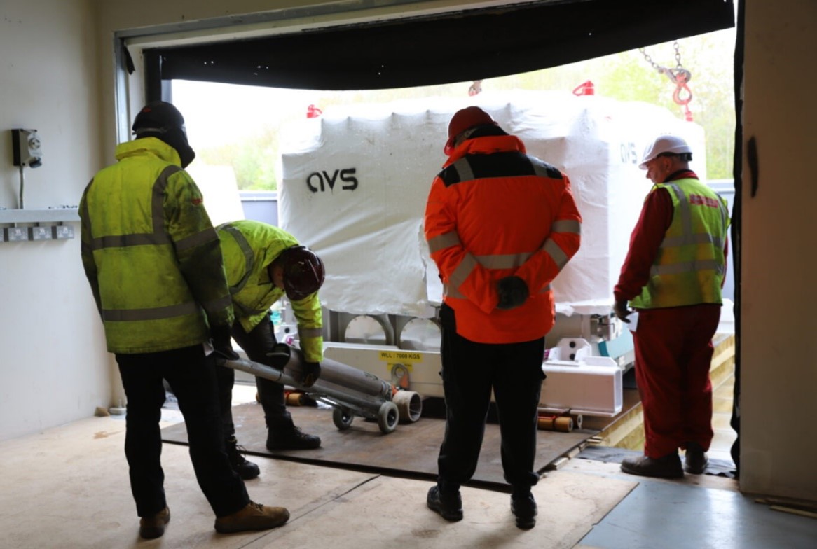
Figure 6: Posting the chamber through a wall opening on the second floor of the EPAC building
![]()
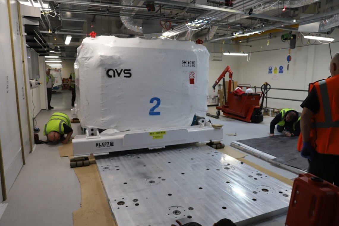
Figure 7: Aligning the chamber on the baseplate
![]()
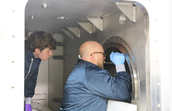
Figure 8: Carrying out inspections
![]()
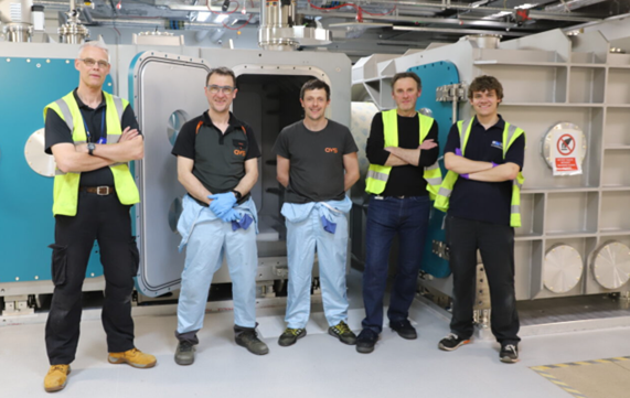
Figure 9: The team successfully installed the chambers to 0.5mm nominal position, with breadboard
flatness to 100 microns over 4.2 m2 in just four days
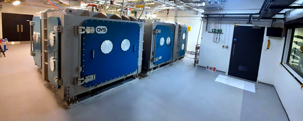
Figure 10: The installed compressor chambers, with a combined weight of over 26 tonnes,
on the second floor of the EPAC building
Progress towards delivering the EPAC Front End
The EPAC laser will be capable of delivering petawatt pulses of 30 J energy and <30 fs duration at 10 Hz repetition rate. These short pulses are first generated with relatively low energy in the Front End. In the Front End room, pulses are amplified by a factor of >109 to the joule level while preserving pulse quality in a process known as optical parametric chirped-pulse amplification (OPCPA), before being transported to the high energy Ti:Sapphire amplifier room.
The pulse energy and beam profile characteristics in an OPCPA system are heavily dependent on the pump lasers that are synchronously overlapped with the short-pulse beamline in optical amplifiers. The EPAC team has worked closely with pump laser manufacturers to deliver stable and high-quality pump sources for the EPAC Front End, with the short-pulse beamline being designed and built entirely by the CLF. The beamlines are designed to be operated remotely via motorised key optics and an EPICS-based control system connected to all devices in the laser, including an extensive suite of optical diagnostics throughout the beamline.
![]()
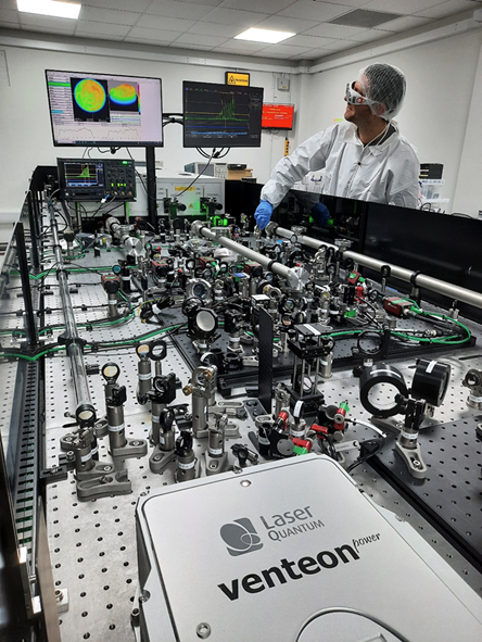
Figure 11: The picosecond pumped OPCPA sub-system of the EPAC Front End, where pulses
are amplified to the millijoule level before being stretched to nanoseconds in duration
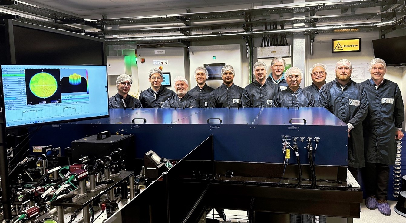 Figure 12: The installation team of scientists and engineers for the Gigashot Nd:YLF diode-pumped laser,
manufactured by Cutting Edge Optronics. This laser is capable of generating 7 J pumping pulses at
10 Hz repetition rate for the high-energy OPCPA amplifiers in EPAC.